11. Makeblock Co., Ltd. Technical support: [email protected] www .mak eblock .com @Makeblock @Makeblock @Makeblock
1.
3. 4×8×4 mm Copper Bushing (1) 1:1 M4×8 mm Screw (2) 1:1 M4×8 mm Screw (1) 1 5 7 8 6 Smart Servo (1)
2. Building Instruction 1:1 M4×8 mm Screw (2) M4 Nut (2) Smart Servo (1) 1:1 M4×8 mm Screw (2) 1 3 4 2 4×8×4 mm Copper Bushing (1) MEDS150 Servo Motor Bracket (2)
4. 1:1 M4×8 mm Screw (1) 9 11 12 10 1:1 1:1 M4×8 mm Screw (2) Smart Servo Mounting Bracket (1) M4×8 mm Screw (2) Plastic Spacer 4 x 7 x 2 (2) 0824 - 032 Beam (1)
5. 13 15 16 14 Footpad (1) Dragoon Foot (2) 1:1 M4×8 mm Screw (3) Dragoon main part (1) 1:1 Nylon Lock Nut 4mm (5) M4×16 mm Screw (5) 1:1 M4×8 mm Screw (2) The dragoon's body has a frosted surface facing outwards, and the smooth surface contacts the legs. The direction of the two servo gears should be consistent with the figure. Plastic Spacer 4 x 7 x 2 (2) Repeat steps 1 ~ 14 to complete the construction of the remaining three legs of the Dragoon.
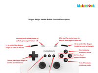
10. Wiring Instruction Complete the wiring with instruction below. Me Ultrasonic Sensor should be connected to Auriga port 10. Me Touch should be connected to Auriga port 9. Servo No.4 Servo No.1 Servo No.3 Servo No.2 Smart Servo Driver Servo No.7 Servo No.8 Servo No.6 Servo No.5 IN(Red) IN(Red) AA Battery IN(Red) IN Interface OUT3 OUT2 OUT5 OUT1 IN(Red) IN(Red) IN(Red) IN(Red)
9. 29 31 30 Velcro (1) AA Battery Holder(1) Building Complete! Servo No.1 Servo No.3 Servo No.4 Servo No.5 Servo No.6 Servo No.8 Servo No.7 Servo No.2
8. Me Touch Sensor (1) 1:1 M4×8 mm Screw (1) 1:1 M4×8 mm Screw (2) 1:1 M4×8 mm Screw (2) 25 27 28 26 M4 Nut (2) 0824 - 016 Beam (1) Me Auriga power connector should toward Dragon Knight tail. Before installing the cover, please connect the Bluetooth module. Thread a black servo line into place.
7. 1:1 M4×8 mm Screw (12) 21 23 24 22 Me Auriga (1) Dragoon main part (1) Dragon Knight main body installation direction is consistent with the other main body bracket. Insert white terminal of black servo line.
6. Smart Servo Driver (1) 1:1 M4×8 mm Screw (2) 1:1 M4×8 mm Screw (9) 17 19 20 18 M4 Nut (2) Plastic Rivet (4) 1:1 M4×16 mm Screw (2) 0824 - 016 Beam (1) Me Ultrasonic Sensor (1) Dragoon front Tail The Smart Servo gear driver module switch should be installed at the tail of the dragoon. Head
Views
-
1046
Total Views
-
959
Website Views
-
87
Embeded Views
Actions
-
0
Social Shares
-
0
Likes
-
0
Dislikes
-
0
Comments
Share count
-
0
Facebook
-
Twitter
-
0
LinkedIn
-
0
Google+
Embeds
2
-
5
uus.insplay.eu
-
3
51.83.143.171